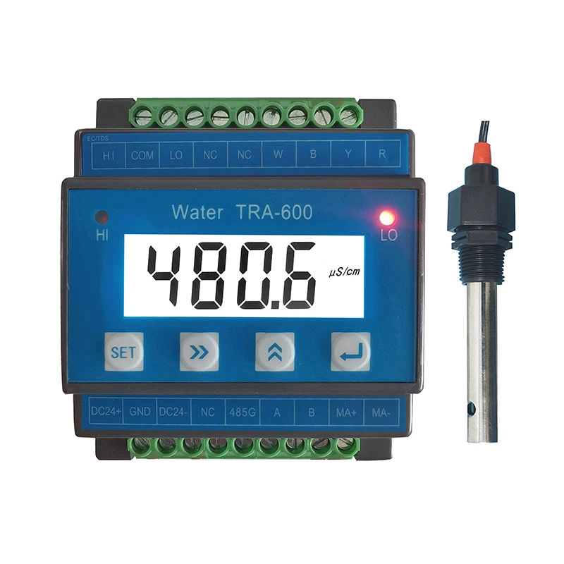
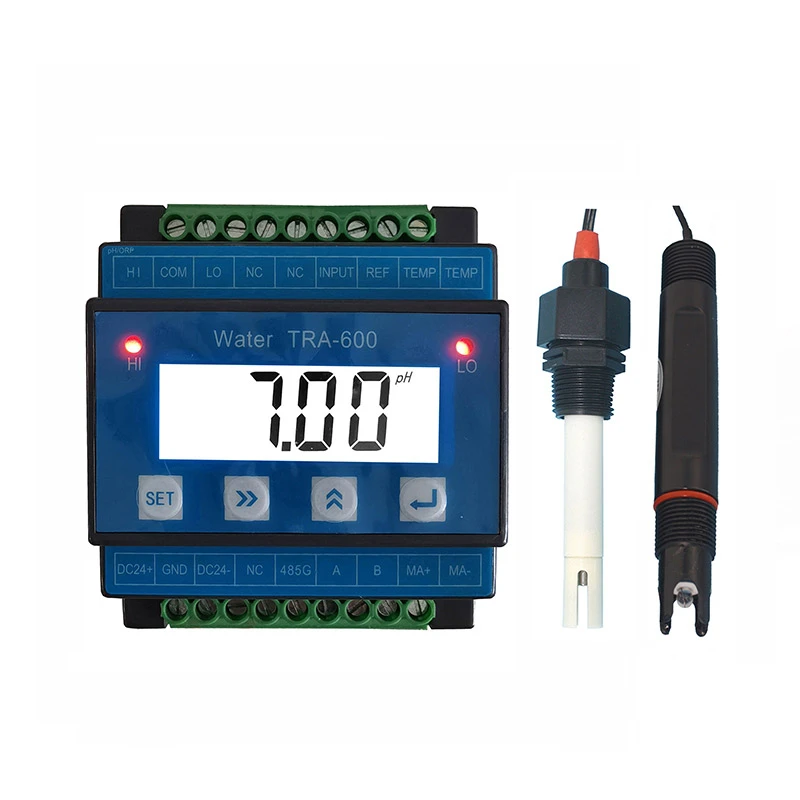
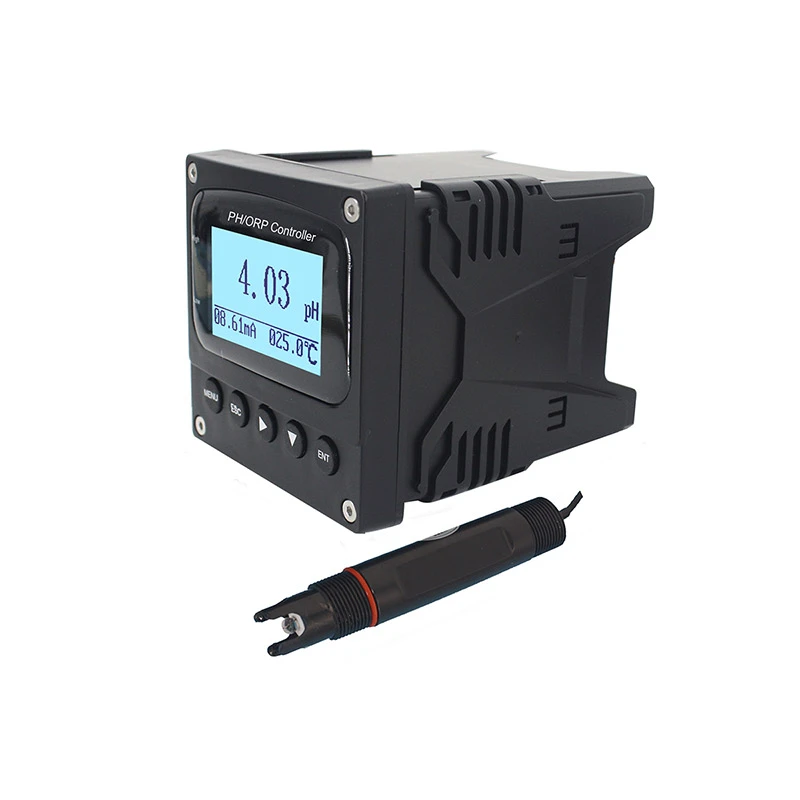
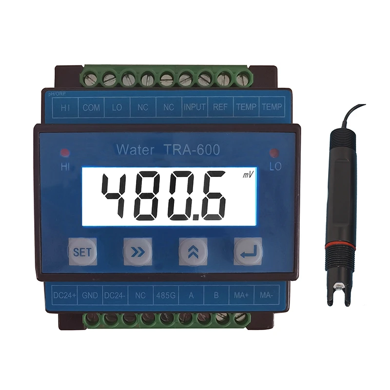
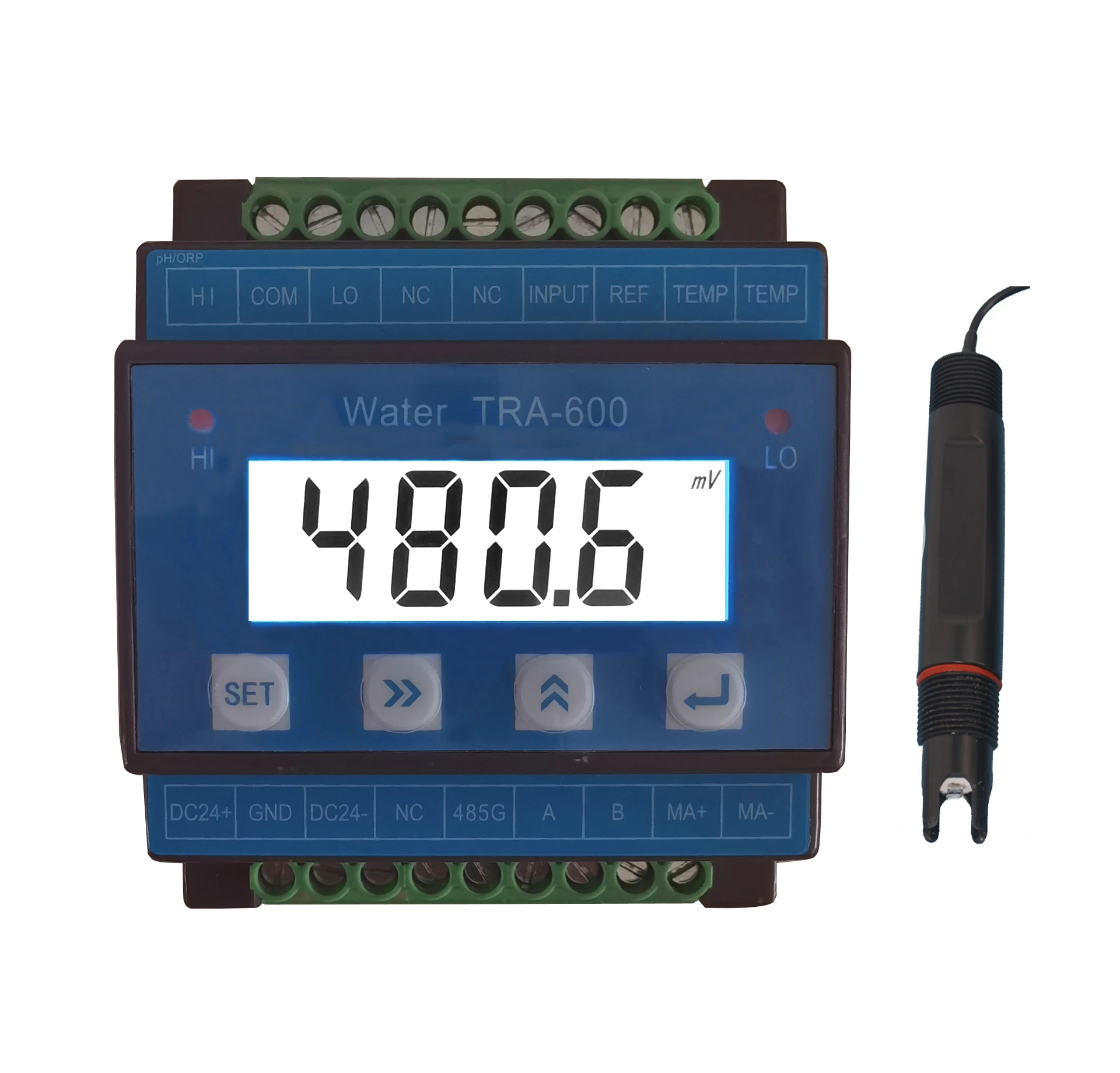
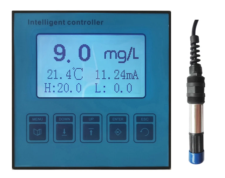
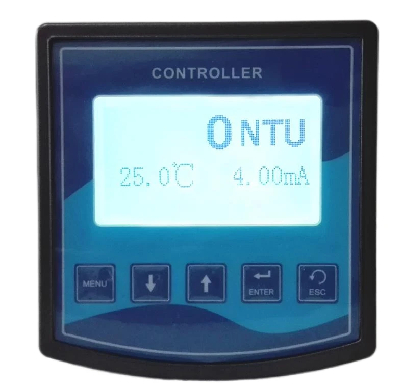
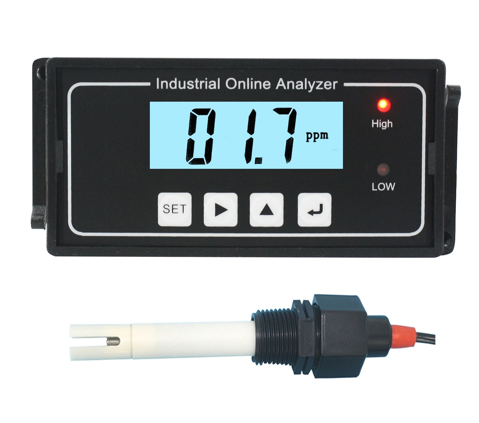
Major Technical Specifications
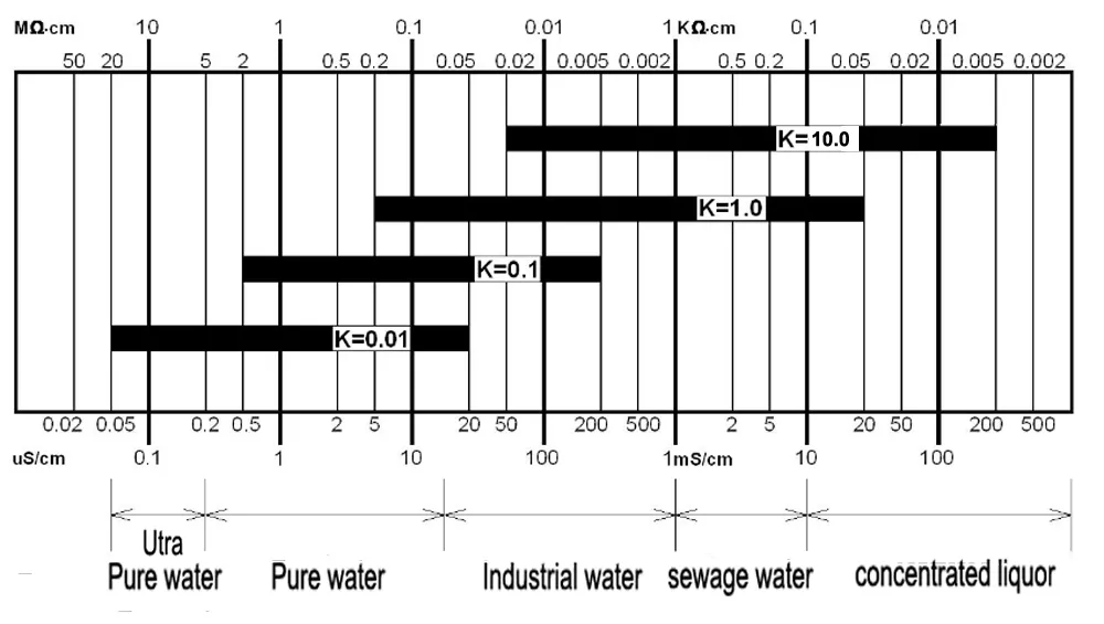
Measuring range:
0~200uS/cm □, 0~ 100ppm □, K=0.1 or 1.0cm-1
0~2000uS/cm □, 0~1000ppm □, K=0.1 or 1.0cm-1
0~4000uS/cm □, 0~2000ppm □, K=1.0cm-1
0~20mS □, 0~9999ppm □, K=1.0 or 10.0cm-1
| Displaying mode |
LCD |
| Accuracy |
1.5%(FS) |
| Stability |
±2×10⁻³(FS)/24h |
| Working pressure |
0~0.5MPa |
| Medium’s temperature |
0~50℃ |
| Temperature compensation |
Auto |
| Provided electrodes |
1.0cm-1 electrodes (0.1cm-1 constant optional) |
| Length of the cable |
4.5m or otherwise agreed m |
| Control output |
Maxi. and Mini. (constantly open) contact point |
| Capacity of contact points |
3A/AC250V (with resistant loads) |
| Output |
4-20mA current or RS485 (optional) |
| Power supply |
DC-24V ,0.5A □; (Standard) DC-12V,0.5A □ (optional) |
| Environmental conditions |
Humidity: ≤85%/RH; Temp.: 0~50℃ |
| External dimensions |
92*76*59mm (H x W x D) |
| Installation mode |
DIN Installation |
Wire Connection
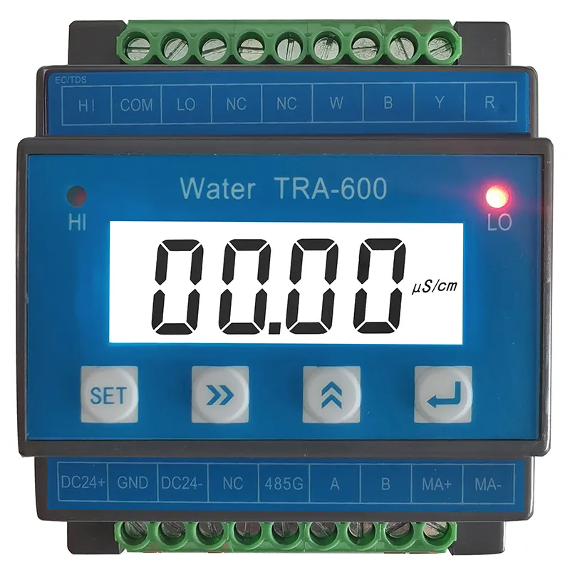
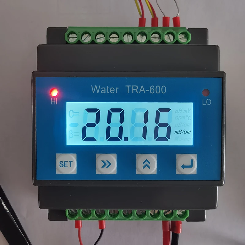
EC/TDS/mS shift to display
A Terminals
|
No.
|
Terminal
|
Terminal Content
|
|
1
|
HI
|
Constantly open high limit relay alarm output
|
|
2
|
COM
|
Relay common terminal
|
|
3
|
LO
|
Constantly open low limit relay alarm output
|
|
4
|
NC
|
Empty
|
|
5
|
NC
|
Empty
|
|
6
|
INPUT
|
EC/TDS electrode signal input( White wire)
|
|
7
|
REF
|
EC/TDS electrode signal ground wire( Black)
|
|
8
|
TEMP
|
Auto Temp. compensation measuring wire(Yellow)
|
|
9
|
TEMP
|
Auto Temp. compensation measuring wire(Red)
|
B Terminals
|
No.
|
Terminal
|
Terminal Content
|
|
1
|
DC 24+
|
Power input +
|
|
2
|
GND
|
Equipment Ground wire
|
|
3
|
DC 24-
|
Power input -
|
|
4
|
NC
|
Empty
|
|
5
|
485G
|
RS 485 Signal Ground wire
|
|
6
|
A
|
RS485 Signal A
|
|
7
|
B
|
RS485 Signal B
|
|
8
|
MA+
|
4-20mA current signal output +
|
|
9
|
MA-
|
4-20mA current signal output -
|
Operation Of The Instrument
1) Soft key function
|
Soft key
|
Key function
|
Function description
|
|

|
Menu Key
|
Under Measuring status, Enter or exit related parameter “setting Menu”
|
|

|
Right shift key
|
Right Shift to select the digit of the parameter(Number flashes When selected); Up shift to browse Menu.
|
|

|
Add shift key
|
Change the selected parameter digital value and parameter shift
|
|

|
Confirm key
|
Confirm to select and enter into Menu and parameter save, check the temp. value.
|
2)Operation of the Instrument
Under main interface, Press“ ”key to Menu interface, detail as below
|
No.
|
Menu
|
Menu Content
|
|
1
|
Un-T
|
Measuring Unit: ppm /uS shift to display
|
|
2
|
CON
|
Electrode constant input
|
|
3
|
H--C
|
Relay high limit close value
|
|
4
|
HO--
|
Relay high limit open value
|
|
5
|
LC--
|
Relay low limit close value
|
|
6
|
LO--
|
Relay low limit open value
|
|
7
|
DE--
|
delay x second alarm
|
|
8
|
4--A
|
4mA corresponding conductivity value
|
|
9
|
20-A
|
20mA corresponding conductivity value
|
|
10
|
Add--
|
RS485 address
|
|
11
|
BAUD
|
RS485 Baud rate
|
|
12
|
CAL-
|
EC Calibration Menu, one point calibration
Calibration standard: 84uS,1413uS, 12.88mS or any known Conductivity vale solution
|
|
13
|
FAC-
|
Factory setting
|
Note:
After having set an option, you must press the button to save the data.
Installation Of Measuring Electrodes
1)Probe installation:
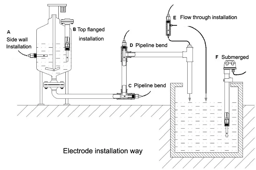
In order to make the electrodes measure correct conductivity in the pipeline, make sure to avoid data inaccuracy caused by the air bulbs or backwater in the conductance cell. Please install strictly according to the following diagram:
2)Common installation way:
The installation of probe is very careful work, the abnormal installation way can’t obtain satisfaction measurement data. During installing the senor, must choose carefully the suitable installation site and installation way to avoid measurement data distortion.
① In figure A, electrode joint is too long, into the part too short, which is easy to form the die cavity, cause to measurement error, must install the electrode according to the Figure B (Face to flow direction and go deep into the flow )
|

Figure A Wrong installation
|

Figure B Correct installation
|
② Figure A installation way will make conductance pool forming air cavity to lead to measurement error and unstable. Must install according to the figure B.
|

Figure A Wrong installation
|

Figure B Correct installation
|
Note: The small round hole need to be in the water outlet port.
③ Other common wrong installation way:

Because of the water flow direction, can’t guarantee the water full in the pipeline, or high air accumulating lead to measurement error or unstable.
3)Attention matters of Electrode Installation and Maintenance:
① Conductivity pool should be installed in the pipeline flow stability and not easy to have bubbles, can adopt the way of flow by installation, in order to avoid inaccurate measurement.
② The horizontal installation, inclined to install or vertical installation need to make the electrode front end face to the flow direction, and deep into the flow of water,
③ The measure signal is weak electric signal, its cable should be contributed separately, it is not allowed to contributed together in same cable or terminal with other power line, control line etc, which is to avoid interrupt or broke the measure unit.
④ If the measure cable need to lengthen, pls contact with the supplier or indicated before place order (generally not longer than 10m)
Electrode Maintenance
(1) The electrode cell should not be soaked in strong acid or alkali liquid, and the platinum black coating should not be
wiped or it will lead to electrode surface damage and the constant and response capability will be affected. The right
way should be: when the electrode is dirty, soak it in 10% dilute hydrochloric acid for a short while, then rinse it with
pure water to keep the surface clean.
(2) The measurement cable is special cable and should not be changed at will or it will cause significant error.
Calibration Interface
The calibration takes the form of One-Point calibration. The automatic calibration protection function work in the process of calibration, illegal calibration is not executed.
Before the calibration starts, make sure that you have prepared well Conductivity standard Solution.
Before the calibration starts, the electrodes must be submerged and activated in clean water or the measured solution for 5 minutes.
The detailed calibration methods are as follows:
1)Press the button  and
and  until the instrument display “CAL-”, and it enters the calibrating state.
2)Press the button  , and the instrument will display “141.3 uS or 1413 uS”.
3)Put the cleaned electrodes into the “84uS or 1413uS or 12.88mS or any Standard solution”, press the button  and
and  to input the known solution conductivity value.
4)Press the button  , the controller display the current buffer solution Value, wait 3 to 5 minutes, when the Conductivity value stable, press the button
  to save.
5)During calibration, if the controller display “ ERR”, which indicate calibration failure, need to re-calibrate, if more times calibration failure, pls change the electrode, or contact with the supplier.
Fault Diagnosis And Trouble Shooting
When the system measurement data is incorrect and unstable, firstly judge the problem is from the meter or from the probe, the easiest way on site is as follows:
1) To distinguish the problem is from the meter or probe, remove the Signal In wire from the meter rear terminal, check whether the conductivity meter shows Zero and stable prove meter is normal, preliminary determination problem from the installation of probe.
2) To just the interference sources from the meter or probe, pls dismantle the sensor’s Signal In and Temp in Wire, and observe whether the conductivity meter display zero stably, if display normal, then, the interference is not from the meter.
3)If conductivity measured value deviation is large, in order to determine the measurement data whether correct or not, take the probe off the pipeline, adopting the clean breaker sampling measurement( Pls see below Note), comparing with laboratory instrument, rule out the factors of temperature compensation, when measuring results are basically identical, can judge the sensor installation form need to change. If offline measurement result still differ greatly, focusing on checking the parameters setting of the meter. ( Pure water can’t use this way).
Note:
High pure water, ultra pure water can’t adopt open sampling measurement way. This is because of in the process of making, not only removing the ions in water, and removing the gas composition. High pure water exposure to air in the moment, immediately there is a lot of carbon dioxide to quickly dissolves in the water, at the same time, the impurity on vessel wall and dust in the air also dissolve in the water, resulting in multiple errors.
High pure water only allowed the use of airtight, flow, side-stream flow cell to verify, laboratory open form measuring high pure water is not correct.
4)Common Faults and exclusion method table
|
Phenomenon
|
Possible causes
|
Recommended solutions
|
|
1.Power on meter,but no display
|
A: Power is not well connected
B: Meter fault
|
A: Check the meter power supply wheter voltage between terminals
B: Pls professional maintenance personnel .
|
|
2.Display is not stable
|
A: Electrode
connection wrong,
B: Bubbles in the pipeline
C: Water quality is not stable
|
A: Change as per operation manual,
B: Correct pipeline or alternate measurement point
C: Exclude the meter problem by stable water sources
|
|
3.Measuring value deviation is large
|
A:
Constant set wrong,
B: Electrode constant change,
C: Measuring point velocity is not appropriate,
D: Electrode instal- lation wrong,
|
A: Reset the electrode constant,
B: Replace new electrode or calibrate electrode constant,
C: Install the electrode in the appropriate velocity place,
D: Install the electrode as per installation manual
|
4-20mA Current Output Formula
The corresponding value of Conductivity in the 4-20mA current output is 0-200uS, but the user can arbitrarily set the corresponding value according to their own requirements to meet industrial control needs.
4-20mA Current Output Formula:
Current Output (mA):I=16×(C-A)/(B-A)+4
Note:
“I” is output current value,4mA≤I≤20mA
“C” is the current conductivity value,0 ≤ C ≤200,000
“A” is set 4mA corresponds to the number
The corresponding value of” B” is set in 20mA
Complete Instrument
| Controller |
1pc |
| Probe |
1pc |
| Fixed clamp |
1pair |
| Operation manual |
1copy |


