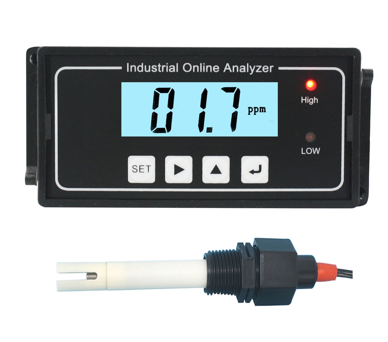
Main Characteristics and Application
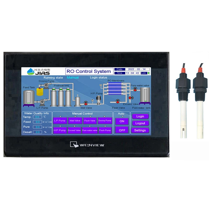
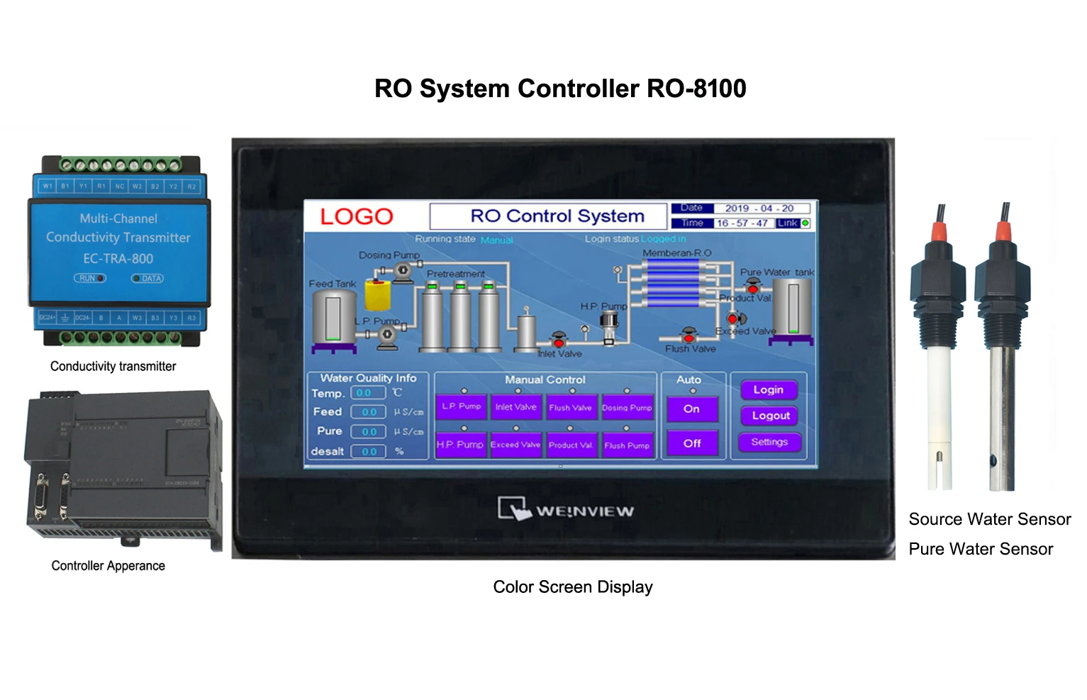
ROS-8100 touch color screen reverse osmosis control system is a multi-function control system with combination of four-wire resistive type touch screen with reverse osmosis process control and online conductivity monitor, it is mainly used for the system control and water quality monitor and control of reverse osmosis system.
The instrument adopts 7-inch (standard version) or 10-inch touch screen (optional version) and 800*480 resolution to realize human-computer information interaction with rich and dynamic display effects.
PLC control and conductivity transmitter acquisition circuit;
Adopt the latest high-speed MCU computer processing system in the United States, real-time control of external IO input and relay output, project design focuses on the system's high stability, high reliability, anti-interference, the characteristics of full digital operation.
The display content of the interface:
Conductivity value monitoring interface, system input signal monitoring, output state display, dynamic system process chart, manual controlling interface, the user setting interface etc. Follow the process state of system in real time, which making the operator could completely control the whole system easily.
The instrument is available in two versions:
Single stage RO control system and double stage RO control system.
The reverse osmosis controller could monitor the conductivity of source water, first stage production water, second stage water production water at same time.
The reverse osmosis controller performs automatic system management, so that the whole system realizes full automatic control and unmanned monitoring, and is adapted to meet pure water equipment and seawater desalination reverse osmosis units in various industries.
Main Technical Index
(For Single Stage Reverse Osmosis System:)
① Collection point of input signal:
Water level of source water tank, this is for checking with or without water.(pipe water supply could be treated as Non-water pressure switch)
Low pressure pump protection
High pressure pump protection
Low pressure switch(before the high pressure pump)
High pressure switch(after the high pressure pump)
Low level of pure water tank
High level of pure water tank
Communicate switch of pre-treatment; (system standby when pre-treatment working)
Note:
High and low level of pure water tank, such as the duckbill switch need to install two switches, two switches directly connected to the high and low liquid level end; if the float switch is used, the high and low liquid level two wires are wired together.
② Controlling point of output:
Source water pump
High pressure pump
Dosing pump
Inlet valve
Outlet valve
Flush valve
Over-limit discharge valve of produced water
conductivity
Alarm relay (can connect with audible and visual alarm)
Note: Solenoid valve requires AC 220V power supply
③ Conductivity measurement
Source water conductivity : 0~5000μS/cm;
Conductivity of RO production water :0~200μS/cm;
Temperature measurement: 0-60℃
Conductivity sensor: 1.0cm-1, cable length 4.5m
④ Other parameters
Power supply:
Controller input: AC 220V/2A
Load capacity of relay output connection: Passive output
Precision: 1.5 level
Working pressure of conductance:0~0.5Mpa;
Temperature compensation: temperature compensation is calculated based on 25℃
7” Screen outline dimension:
200.4 ×146.5 x34mm (width × H x D)
7” Screen hole size:192 x 138mm (Width x High)
10” Screen outline dimension:
271×213 x36.4mm (Width × H x D)
10” Screen hole size:260 x 202mm (Width x High)
Installation: Panel mounted
Controller outline dimension:
140mm x80mm x 62mm(Wx H x D)
Controller installation way: Guide rail mounted
Front Panel
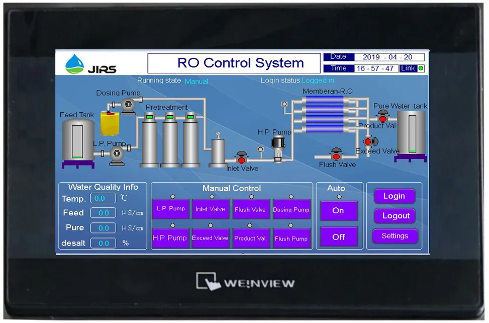
Color Touch Screen Appearance
|
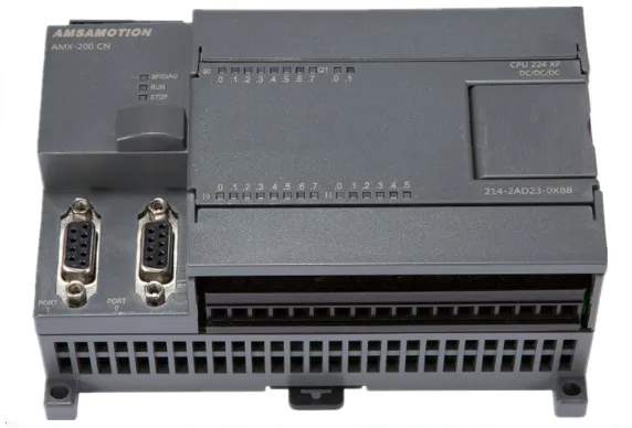
Controller Apparance
|
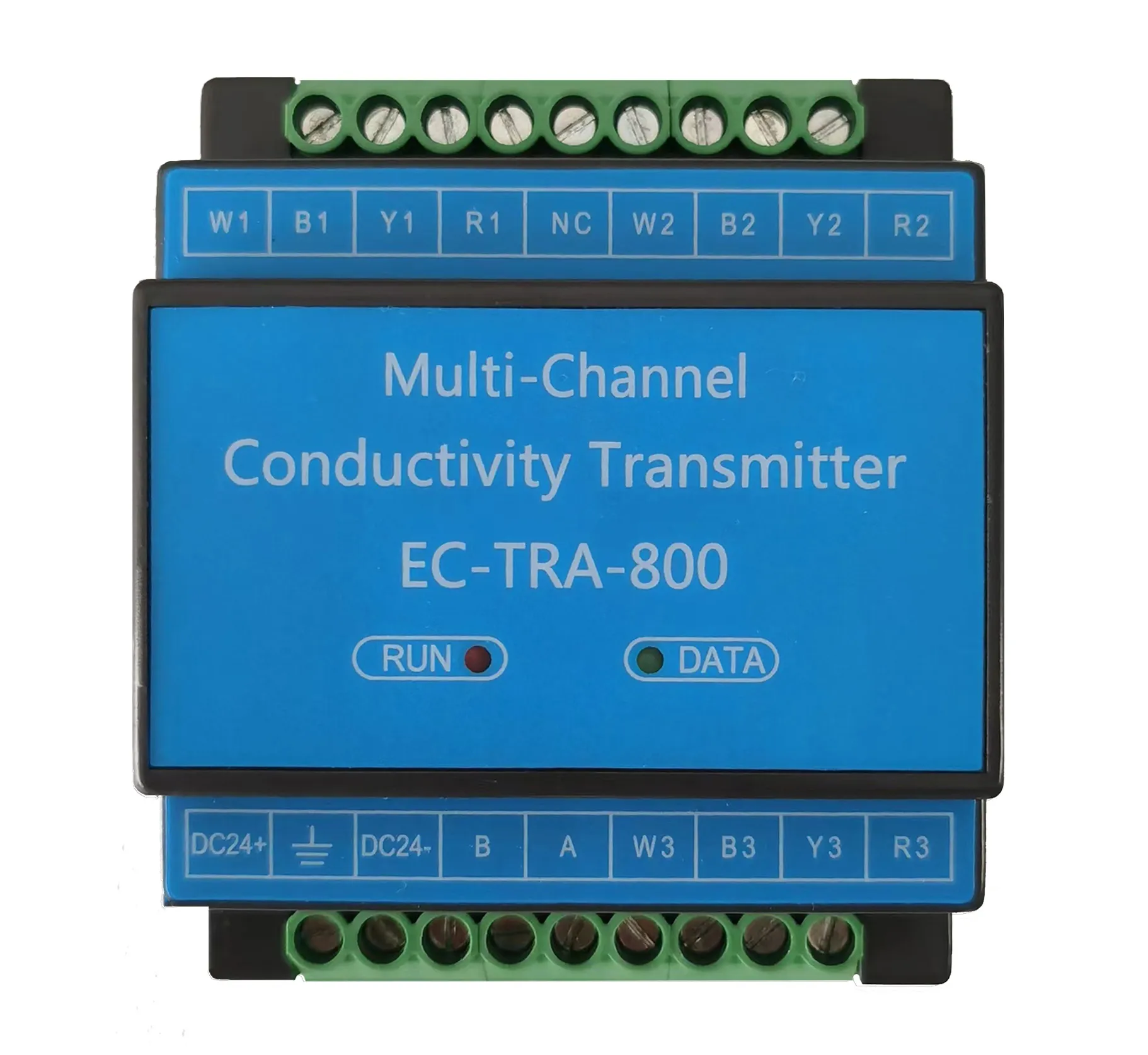
Conductivity transmitter
|
Connection Diagram of System host
1.Connection diagram of Touch color screen display, Reverse osmosis controller and Conductivity transmitter.
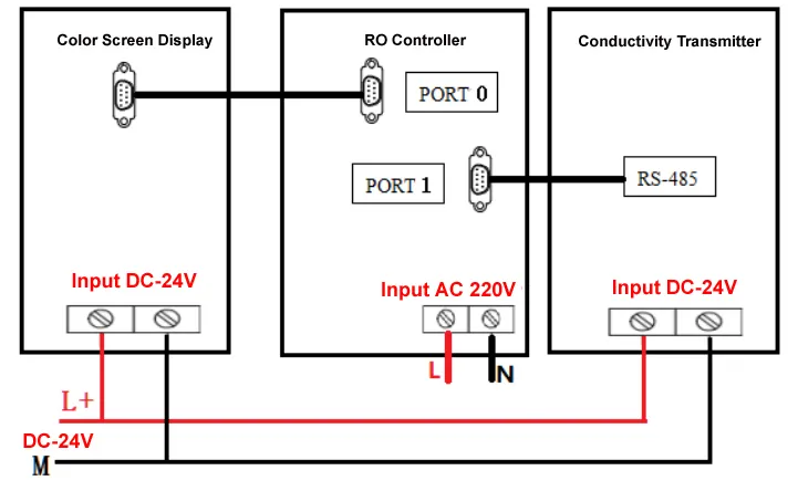
Note: A separate switching power supply, DC 24V/2A, is required to power the color screen and conductivity transmitter.
2、RO Controller detailed description:

(1)Relay control output:
All output ports are 220V relay output, load current is 2A, solenoid valve requires 220V power supply
|
No.
|
Name
|
Detailed description
|
|
1
|
Q-0.0
|
Low pressure pump
|
|
2
|
Q-0.1
|
Inlet valve - 1
|
|
3
|
Q-0.2
|
High pressure pump - 1
|
|
4
|
Q-0.3
|
Flush valve
|
|
5
|
Q-0.4
|
Outlet valve
|
|
6
|
Q-0.5
|
Exceed valve
|
|
7
|
Q-0.6
|
Dosing pump
|
|
8
|
Q-0.7
|
Flush pump
|
|
9
|
Q-1.0
|
Fault Alarm lamp
|
(2)Detection signal input
|
No.
|
Name
|
Detailed description
|
|
1
|
I-0.0
|
Source tank level switch, normally open contact,
Disconnected without water, connect when there is water.
|
|
2
|
I-0.1
|
Low pressure pump protection, normally open contact,
Normally open, closed when overloaded
|
|
3
|
I-0.2
|
High pressure pump protection, normally open contact,
Normally open, closed when overloaded
|
|
4
|
I-0.3
|
Low-voltage switch, normally open contact,
Open when the pressure is less than the set value,
Closed when the pressure is more than the set value
|
|
5
|
I-0.4
|
High-voltage switch, normally open contact,
Open when the pressure is less than the set value,
Closed when the pressure is more than the set value
|
|
6
|
I-0.5
|
Pure water tank Middle liquid level, normally open contact,
Disconnected without water, connect when there is water.
|
|
7
|
I-0.6
|
Pure water tank high liquid level, normally open contact,
Disconnected without water, connect when there is water.
|
|
8
|
I-0.7
|
Pre-treatment signal, normally open contact,
Normally open contact, closed during pre-treatment flushing
(connected to pre-treatment automatic flush valve)
|
|
9
|
I-1.0
|
Emergency stop switch, normally open contact,
Normally open, close during emergency stop
|
(3)PORT 0: PLC and touch color display communication interface (4)PORT1: PLC and Conductivity transmitter communication interface;
(5)AC-220V power supply: L1、N
(6)DC24V output :L+、M
Note:
Due to the use of small relays (0.5A/220V,0.5A/24V DC ) in the controller, intermediate relays or contactors must be used when driving large inductive loads, and cannot be directly driven.
3、Transmitter terminal description:
A Terminals:
|
No.
|
Name
|
Detailed description
|
|
1
|
W1
|
Source Water Conductivity white wire
|
|
2
|
B1
|
Source Water Conductivity Black wire
|
|
3
|
Y1
|
Source Water Conductivity Yellow wire
|
|
4
|
R1
|
Source Water Conductivity Red wire
|
|
5
|
NC
|
Empty
|
|
6
|
W2
|
1st Stage Produced Water Conductivity white wire
|
|
7
|
B2
|
1st Stage Produced Water Conductivity Black wire
|
|
8
|
Y2
|
1st Stage Produced Water Conductivity Yellow wire
|
|
9
|
R2
|
1st Stage Produced Water Conductivity Red wire
|
B Terminals:
|
No.
|
Name
|
Detailed description
|
|
1
|
DC 24V +
|
Power supply positive
|
|
2
|
GND
|
Grould wire
|
|
3
|
DC 24V -
|
Power supply negative
|
|
4
|
485B
|
RS-485 B terminal
|
|
5
|
485A
|
RS-485 A terminal
|
|
6
|
W3
|
NC
|
|
7
|
B3
|
NC
|
|
8
|
Y3
|
NC
|
|
9
|
R3
|
NC
|
Single stage RO System process
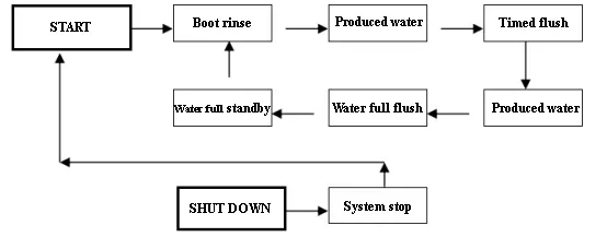
System Operation Interface
1、Install and connect wires correctly and connected each parts, make sure power input wire connection is correct, then turn on the power, the instrument will make a drop sound, after 5 seconds, the instrument screen enter into the system control interface directly, as showed in chart 1.
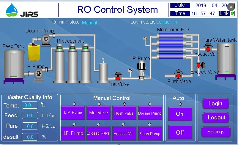
Chart 1 System control interface
System Control Interface Description
|
No.
|
Name
|
Detailed description
|
|
1
|
Running status
|
Automatic, Manual, Produce water, Standby, flushing, etc.
|
|
2
|
Login status
|
Logged in, Logout
|
|
3
|
Alarm status
|
Scrolling display system current alarm status: Soure water tank low water level, excessive conductivity, etc.
|
|
4
|
System flow chart
|
Display the running status of the device through the panel LED display status red or green
|
|
5
|
Water quality info
|
Temperature, Raw water conductivity, Pure water conductivity, desalination rate value
|
|
6
|
Manual control
|
Manual operation (optional):
Low pressure pump, inlet valve, flush valve, dosing pump, high pressure pump, Excessive valve, pure water valve
|
|
7
|
Automatic start
|
"Start / Shutdown" autorun function
|
|
8
|
Logged in
|
Select user identity login control system
|
|
9
|
Logout
|
Exit control system
|
|
10
|
Setting
|
Control system parameter settings
|
Note: The display status light green indicates the selected status.
- The system controller is in standby mode. Please log in before operating the controller. Clicking Loginwill bring up the login dialog, as shown in Chart 2;
-
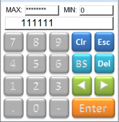
Chart 2 System Login interface
Select the " user " identity, enter the " 111111 " password to log in successfully, you can operate the controller.
3、After logging in, the system is in a shutdown state, the system defaults to manual mode. When the system is in a shutdown state, the following device switches (shown in Chart 3) can perform manual independent operations. When “Auto” is turned on, the system starts to run automatically, and the manual operation device is invalid.

Chart 3 Manual Control Interface
5、The upper right corner of the interface is the time and date of the system. The parameter has been adjusted correctly at the factory, and the user does not need to adjust it, as shown in Chart 4 below.

Chart 4 System Time and Date interface
6、Parameter setting interface, system display:
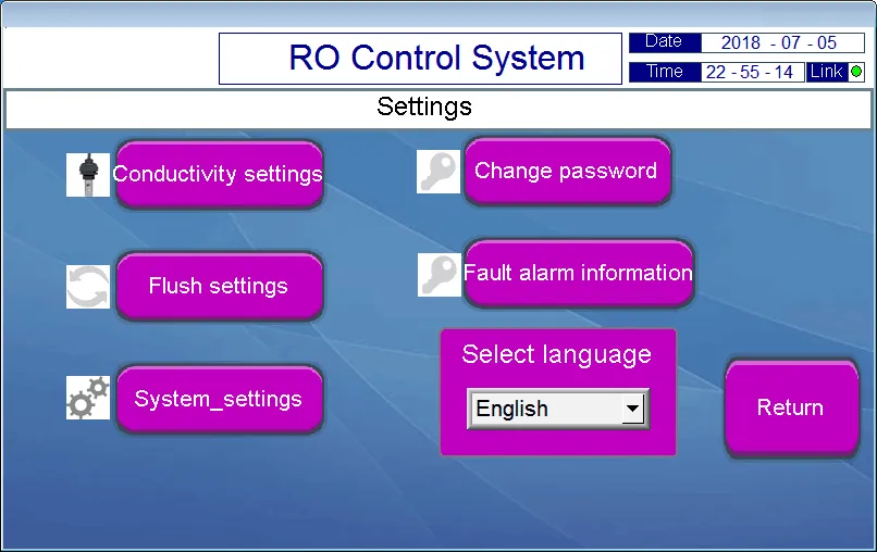
Chart 5 Parameter setting interface
Parameter setting interface description:
|
No.
|
Name
|
Detailed description
|
|
1
|
Conductivity settings
|
The display of conductivity values, conductivity over-standard values and electrode constant settings, as shown in Chart 6 &7
|
|
2
|
Flush settings
|
Startup flushing, full flushing, timed flushing, interval flushing time setting, as shown in Chart 8.
|
|
3
|
System settings
|
System running time, high pressure pump status setting during pre-treatment and flushing, high pressure pump start, outlet valve start and low pressure protection delay setting, as shown in Chart 9.
|
|
4
|
Change password
|
Password modification settings, as shown in Chart 10.
|
|
5
|
Fault alarm information
|
Fault alarm information query that occurs during system operation, as shown in Chart 10
|
|
6
|
Select language
|
Chinese, English, Persian
|
|
7
|
Return
|
Return to system control interface
|
7、Conductivity settings interface:
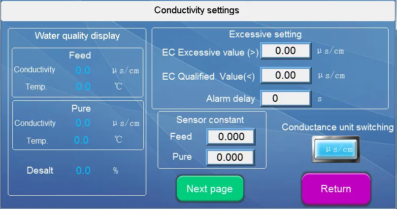
Chart 6 Conductivity setting interface
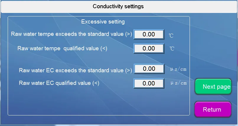
Chart 7 Conductivity setting interface
8、Flushing settings interface:
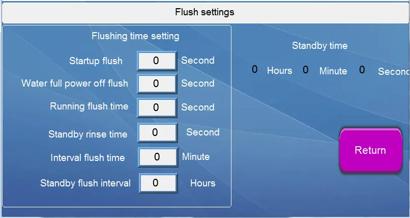
Chart 8 Flushing setting interface
9、System setting interface
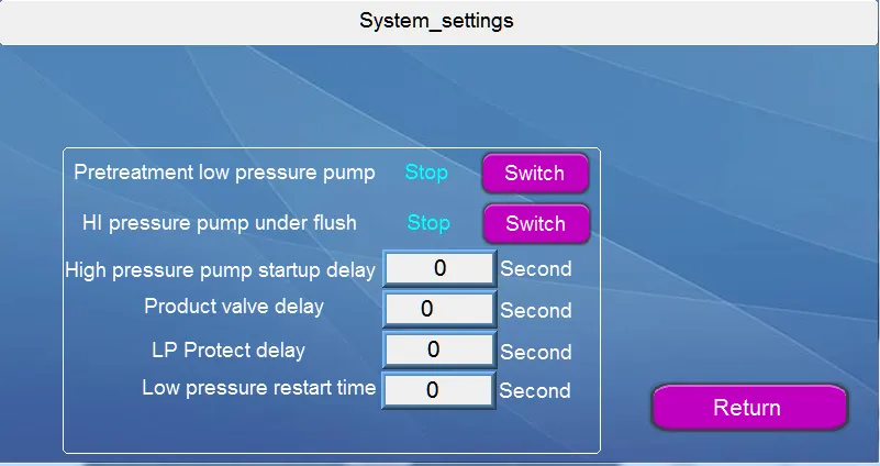
Chart 9 System setting interface
10、Change password interface:
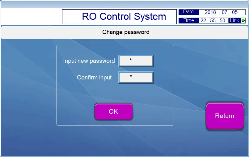
Chart 10 Change password interface
10、 Fault alarm information interface:
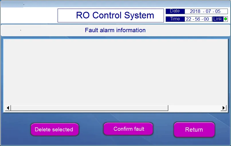
Chart 10 Fault alarm information interface
Installation of the sensors
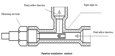
To ensure the real measurement result, data distortion caused by air bubble or dead water in conductance cell should be avoided. The installation should be performed strictly according to the following drawing:
|

Sensor Apperance
|
 |
Notes:
(1)The sensor should be installed at a lower location inthe pipe where the flow speed is steady and air bubbles are seldom generated.
(2) No matter the conductance cell is horizontally or vertially installed, it should be deeply inserted into the moving water.
(3) The conductivity signal is weak electronic signal and collecting cable should be separately installed. They should not be connected to the same group of cable joint or terminal board with the power line.
(4)When the measurement cable needs to be lengthened, it’s recommended to use the cable provided by the original manufacturer, When a longer distance is involved, the length of the cable (<30m) should be agreed on before delivery, and if the length is over 30m, a transmitter should be used.
Trouble shooting
|
Trouble
|
Troubles shooting
|
|
Touch screen don’t display or indicate lamp don’t light
|
To check DC 24V power supply is normal, as well as the power transformer is normal?
|
|
Conductivity excessive alarm
|
① Current measured value > Alarm setting value
② Sensor connection is wrong
|
|
Conductivity measuring value big deviation
|
① Sensor connection is wrong, check the temperature measuring is correct ?
② Conductivity electrode damage
③ Set the wrong electrode constant,
④Field with frequency converter or other power interface, can separate the power supply test.
|
|
Low pressure, high pressure, water level, Sewage water alarm
|
Signal input problem, short circuit controller’s signal input terminals to check.
|
|
In the pretreatment
|
Pre treatment signals are connected
|
|
Communication error
|
To check the communication between the controller and touch screen loose wire or fracture.
|
|
Other troubles
|
Pls contact with factory or distributor
|
Complete Instrument Set
|
Display screen
|
1pc
|
|
Controller
|
1pc
|
|
Electrical wiring diagram
|
1pc
|
|
EC/Conductivity transmitter
|
1pc
|
|
Conductivity Sensors
|
2pcs x 1.0cm-1
|
|
Manual
|
1pc
|


