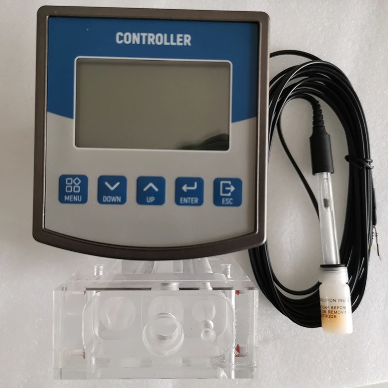
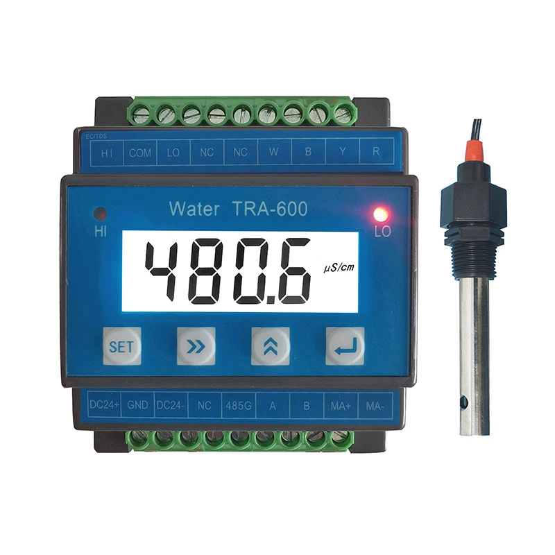
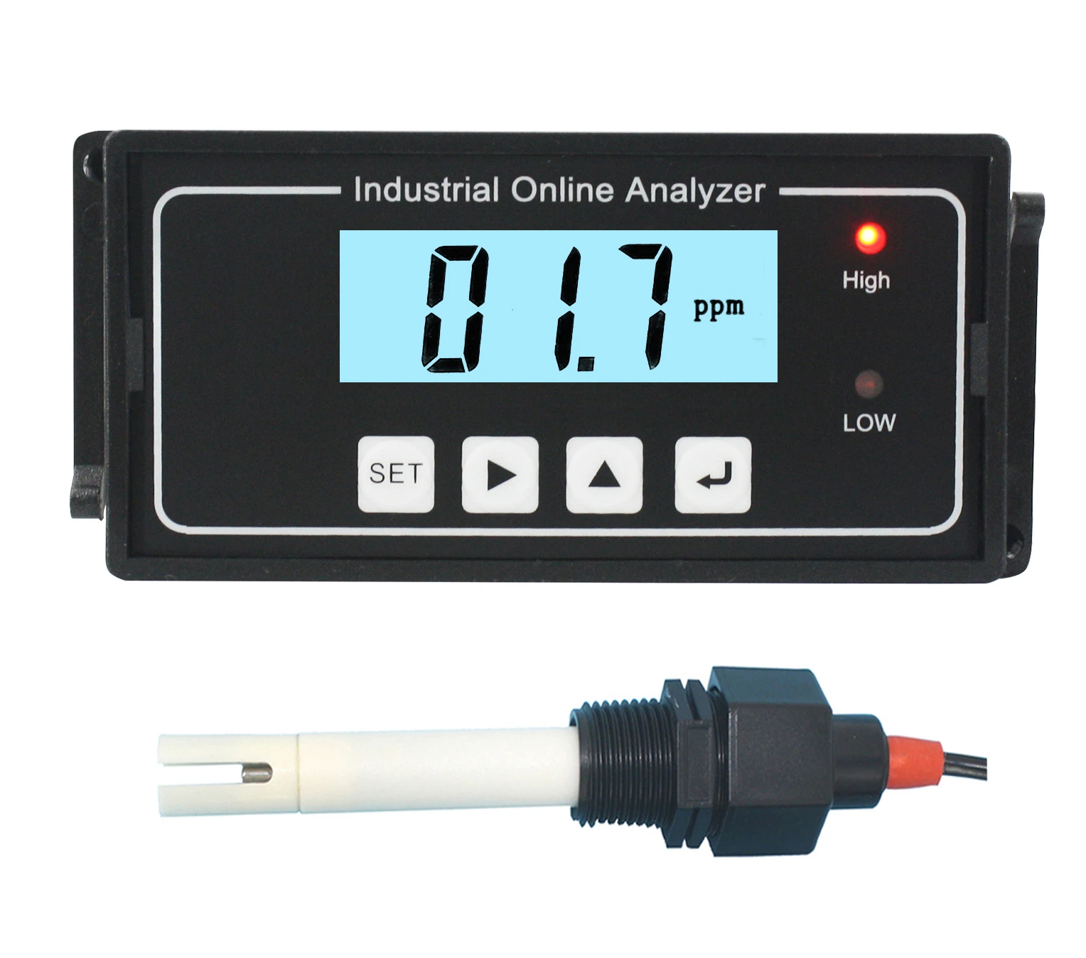
Main Features
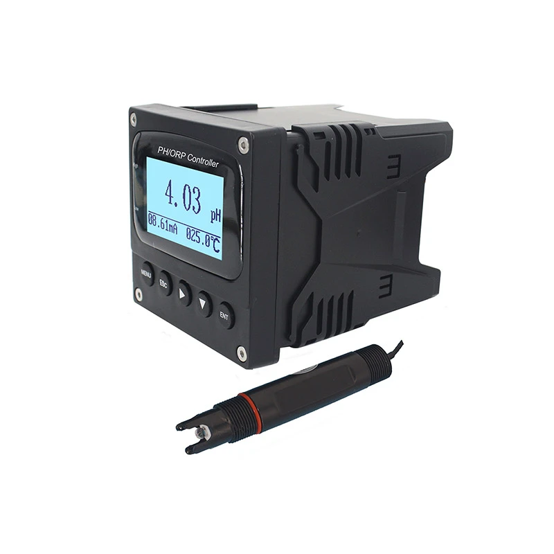
- * Large screen LCD display, English menu (switching from each other).
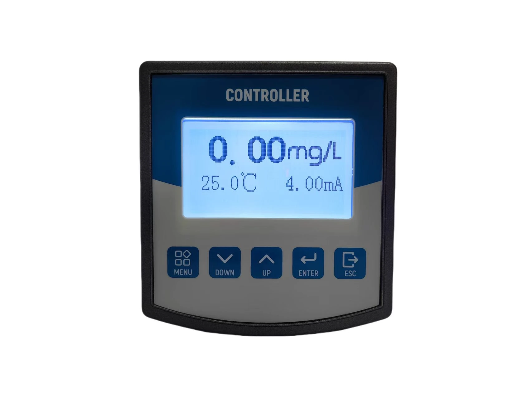
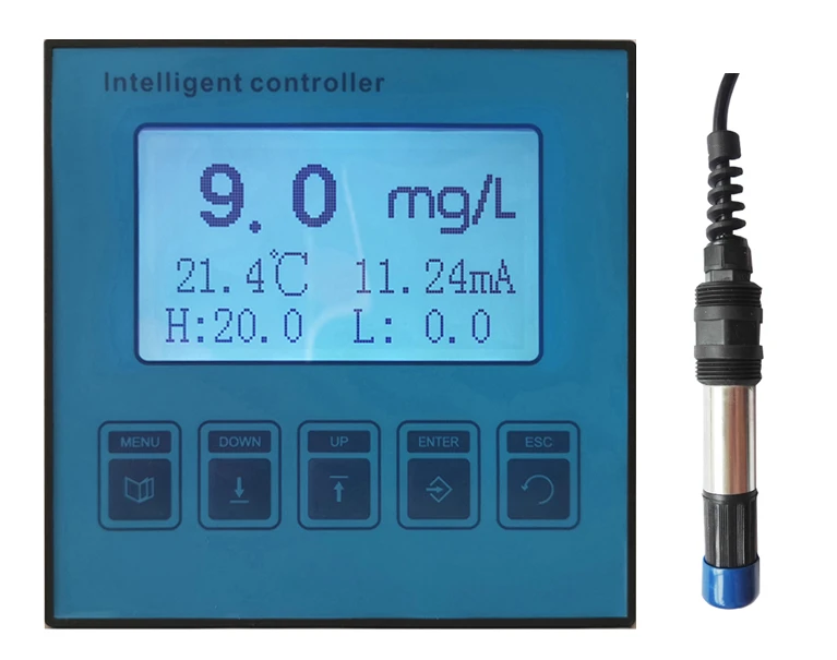
- * Simultaneous display of multiple parameters: residual chlorine value, temperature, output current, etc. are displayed at the same time, which is intuitive and easy to read, and has a range over limit prompt.
- * Capable for factory reset.
- * Automatic&manual adjustmen temperature compensation function.
- * Communicate function: RS-485 communication interface (optional, MODBUS protocol partially compatible). 4-20mA current output can be arbitrarily set.
- * Photoelectric isolation 4-20mA current output.
- * The hysteresis amount can be arbitrarily set to avoid frequent switching of the switching relays.
- * Watchdog function: make sure the meter doesn't crash.
- * Power off protects>10 years.
Technical Indicators
- * Measuring range: residual chlorine: 0-20.00mg/L(ppm), temperature: 0~60°C.
- * Resolution: 0.01mg/L, 0.1°C
- * Accuracy: better than ±1% or ±0.01 mg/L, ±0.5°C
- * Manual/automatic temperature compensation (0~60°C)
- * Control interface: two sets of ON/OFF relay contacts, which are divided into high-point and low-point alarm signals. The third group of relays: automatic cleaning control function analog output.
- * Signal isolated output: optocoupler isolation protection 4~20mA signal output.
- * Relay: The relay hysteresis is arbitrarily set, and the relay load is 3A 220VAC/24VDC.
- * Working conditions: ambient temperature is 0~60°C, relative humidity ≤90%.
- * Output load: Load <500Ω (0-10mA), load<750Ω (4-20mA).
- * Working voltage: 220VAC10%, 50/60Hz.
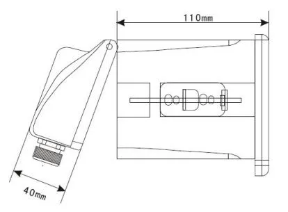
- * Size: 96×105×168 mm.
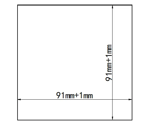
- * Opening size: 92×92mm.
- * Weight: 0.9Kg.
- * Protection level: IP65
Instrument Installation
4.1 Installation of main unit
The instrument should be installed in a clean, dry, well ventilated, vibration-free location with no corrosive gases around it.
1.User need to open a rectangular cutout on the instrument panel or mounting pane.
2.Insert the meter into the instrument cabinet and tighten the locking bars.
4.2 Electrodes
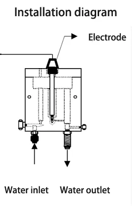
The electrode must be installed in the constant current electrode seat hole of the constant current device if the constant flow device continuously passes water, and ensure that the electrode is always immersed in the water. If the constant current device loses water for a long time, please Take out the sensor and cover it with the original rubber sheath. The rubber sheath must ensure the protective liquid. The specific installation is as follows.
A、Taking out the electrode and carefully push the rubber sleeve of the electrode with your fingernail (note: do not twist it by hand to avoid damaging the electrode) until the rubber sleeve is fully pushed out. Note: If you try to install it temporarily, it is best to save the rubber sleeve and the protective liquid in the sleeve, so that after the test installation, the sampling electrode can cover the rubber sleeve and the protective liquid back to the electrode. The protective solution is slightly corrosive, and if it gets on the skin, it will be rinsed off with water.
B、Inserting the electrode into the constant hole of the constant current device (close to the hole of the water outlet). Be careful not to damage the glass head on the top of the sensor. Be sure to use the raw material tape (threaded part) for waterproof sealing before installation. The on-line monitoring of the measured medium should be kept at a constant flow rate and constant, with a minimum flow of 15 cm3/s.
Instrument Panel And Connection Instructions
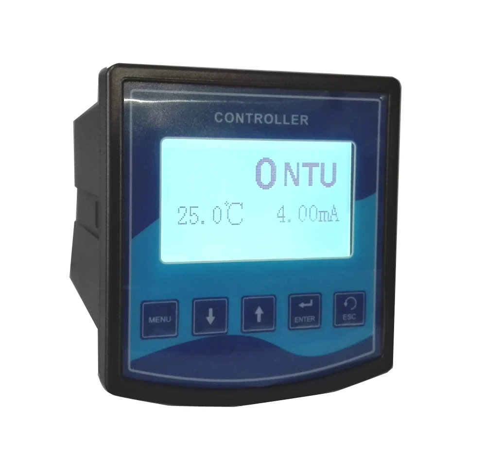
The buttons of front side
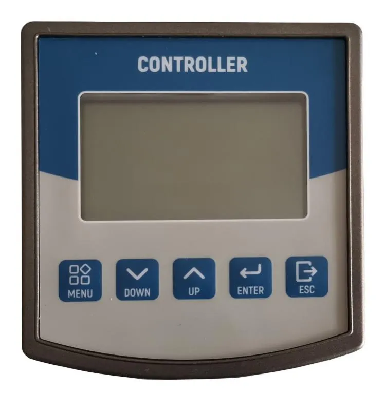
1.MENU 2.DOWN 3.UP 4.ENTER 5.ESC
Wiring instructions for the rear panel
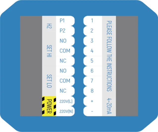
|
P1: H2 relay normally open port
|
1. EL+:(Black wire)
|
|
P2: H2 relay common port
|
2. IN-:(White transparent wire)
|
|
HI NO: High point relay normally open port
|
3.REF: (Yellow wire)
|
|
HI COM: High point relay common port
|
4.Temp
|
|
HI NC: High point relay normally closed port
|
5.Temp
|
|
LO NO: Low point relay normally open port
|
6.empty
|
|
LO COM: Low point relay common port
|
7. RS485 A
|
|
LO NC: Low point relay normally closed port
|
8. RS485 B
|
|
Power: 220V (L)
|
9. 4~20mA+
|
|
Power: 220V (N)
|
10. 4~20mA-
|
Attention: If you needs RS-232 communication, please select the appropriate RS-485 to RS-232 device. The RS-485 interface part of this instrument is compatible with MODBUS protocol. For details, please consult the manufacturer or distributor.
1.Make sure the wiring is correct before powering on. The wrong wiring may cause damage to the instrument.
2.Power can't be bypassed from high-power equipment, power line is separated from signal line.
3.The standard cable of the electrode sensor is 3 meters long. If necessary, the user can extend the cable by himself, but the maximum is no more than 15 meters. For the extension cable, a silver-plated three-core low-resistance cable with shielded wire is required. Extension cords are recommended to be connected with a highly insulated junction box.
Meter Function Setting
6.1 Menu structure
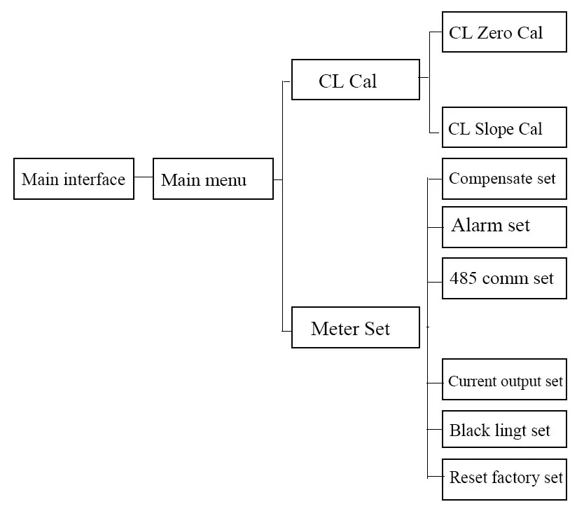
6.2 Main interface and Main menu
The residual chlorine value in the main interface is the main display, and the temperature value and current value are the sub display. Above is the current residual chlorine measurement, 4.12mA is the current output value.
6.3 CL Cal
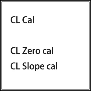
Due to the constant pressure method, the zero potential and the electrode slope of the new residual chlorine electrode are basically the same. no calibration is required during normal use. As the use process will gradually change, resulting in aging, which requires a certain period of "calibration" to ensure measurement accuracy. The menu is as follows:
Press the up and down keys on the main menu to select the residual chlorine calibration, press ENTER to enter the residual chlorine calibration interface.
6.4. CL zero Cal
If you need to calibrate the zero point of the residual chlorine electrode, gently blot the electrode before calibration, place the electrode in the residual chlorine-free water (such as distilled water, purified water, etc.), press the ENTER key to enter the instrument, then press the MENU menu selection key to pop up the cursor, press Up and down key modification
The default value is 0, usually no need to change, wait for stability and press ENTER to save the data. Press the ESC key to return to the previous menu.
6.5. CL slope cal
If you need to calibrate the slope of the residual chlorine electrode. Enter the residual chlorine slope calibration menu. Before calibration, place the residual chlorine electrode in the residual concentration standard chlorine solution, press the ENTER key to enter the instrument, and then press the MENU menu selection key to pop up the cursor. The default value is 0.20mg/L. Press the up and down keys to change it to already Concentration value, such as 0.30mg/L, wait for the residual chlorine value to stabilize and press ENTER to save the data. After the residual chlorine value is stable (±0.01mg/L), it indicates that it has been marked. Press the ESC key to return to the previous menu.
6.6. Compensate set
Pressing the up and down keys in the main menu to select the parameter setting, press ENTER to enter the parameter setting menu, as shown below, the left picture is the first page, and the right picture is the second page. Press the up and down keys to select each setting. The first item is selected in this section.
Press ENTER to enter the compensation setup menu. press the MENU menu selection button to pop up the cursor and move the cursor. press the up and down keys to modify. the temperature is divided into manual or automatic mode. if automatic is selected, the manual value is invalid, and vice versa. when equipped with an NTC thermistor, the true value is measured automatically. if there is no NTC thermistor, you can choose manual input.
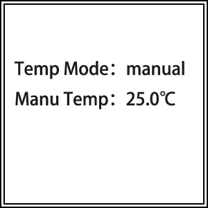
Press ENTER to save the data, press ESC to return to the previous menu.
6.7. Alarm set
Select the alarm setting in the parameter setting menu and press the ENTER key to enter the alarm setting menu. Press the MENU menu selection button to pop up the cursor and move the cursor. You can press the up and down keys to modify it.
In order to avoid the relay from beating or controlling the residual chlorine value, this instrument has this function. The specific operation is as follows:
press the up and down to adjust the hysteresis. That is to adjust the relay hysteresis (customer can adjust in this range according to need, the factory default value is 0.5) After adjusting, press ENTER to store, press ESC to return to the previous menu.
Upper limit relay: will be in the actual measured value higher than the high alarm setting value HIGH value
Time action, when the actual measured value falls below (high point H value - hysteresis H value)
Lower limit relay: It will be operated when the actual measured value is lower than the low alarm set value LOW value, and the actual measured value will rise again when it rises above (low point L value + hysteresis L value). Useful to extend the life of the relay or AC contactor. Therefore, the user must set the high, low and hysteresis according to the actual situation.
6.8. 485 comm Set(optional)
Selecting 485 Communication in the parameter setting menu and press ENTER to enter the 485 communication menu. Press the MENU menu selection button to pop up the cursor and move the cursor.
Press the next button to modify it. The communication address (hexadecimal), press ENTER to store the data, press ESC to return to the previous menu. (Note: Please consult the manufacturer or distributor for specific protocol specifications)
6.9. Current output
The residual chlorine value corresponding to the 4-20 mA output is 0-20 mg/L, but the user can arbitrarily set the corresponding value according to his own requirements to meet the industrial control needs. Press the MENU menu selection button to pop up the cursor, move the cursor, press the up and down keys to modify, press the ENTER key to store the data, press the ESC key to return to the previous menu. Output current (mA): I=16×(C-A)/(B-A)+4
Note: I is the output current value, 4mA≤I≤20mA.
C is the current residual chlorine value measured by the meter, 0.00≤C≤20mg/L.
A is the number corresponding to 4 mA in the setting. B is the value corresponding to 20 mA in the setting.
6.10. Backlight time
Selecting the backlight time in the parameter setting menu and press the ENTER key to enter the backlight setting menu. Press the MENU menu selection button to pop up the cursor and move the cursor. You can press the up and down keys to modify. Press ENTER to store the data, press ESC to return to the previous level.menu. Backlight control allows the meter to save power, protect the display, and extend life
6.11. Reset Factory
In the parameter setting menu, select Restore factory value and press ENTER to enter the factory default menu. Press the MENU menu selection button to pop up the cursor, you can press the up and down keys to modify. Press ENTER to store the data, press ESC to return to the previous menu
Daily maintenance points
The instrument has been calibrated before leaving the factory and can be put into use directly by the user.
The on-line monitoring of the measured medium should be kept at a constant flow rate and constant, with a minimum flow of 15 cm3/s.General instrument failure rate is low
The company provides local after-sales guarantee within one year from the date of sale, but does not include damage caused by improper use. If repair or adjustment is required, please return it, the freight must be paid by yourself, and the package must be confirmed to avoid shipping. Damaged on the way, the company will repair the damage inside the instrument free of charge. (Note: Electrodes and standard solutions are consumables and are not covered by the warranty. The company will guarantee the quality of the electrodes when they are delivered.)


