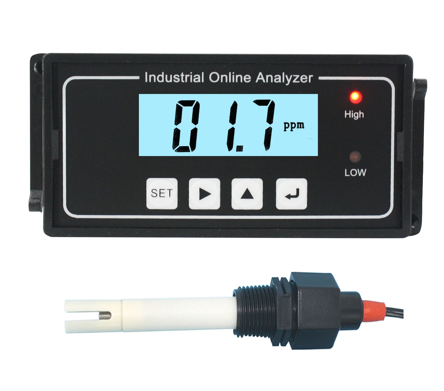
Major Technical Specifications
| Measurement range |
0.000~14.00pH |
| Resolution ratio |
0.02PH |
| Accuracy |
±0.1pH |
| Displaying mode |
3½ LCD |
| Calibrating mode |
Three-point calibration (automatic identification of solutions) |
| Manual temperature compensation |
0~120℃ |
| Compression resistance of electrodes |
0~0.5MPa |
| Measurement distance |
standard configuration 5m(≤40m) |
| Flow Velocity |
≤3m/s |
| Pressure |
≤0.4Mpa |
| Output |
4-20mA current or Modbus RS485 (optional) |
| Control output |
Maxi. and Mini. (constantly open) contact point |
| Capacity of contact points |
3A/AC250V (with resistant loads) |
| Power supply |
DC-24V,0.5A □; (Standard) DC-12V,0.5A □; (Optional) |
| Environmental conditions |
Humidity: ≤85%/RH; Temp.: 0~50℃ |
| External dimensions |
92*76*59mm (H x W x D) |
| Installation mode |
DIN Installation |
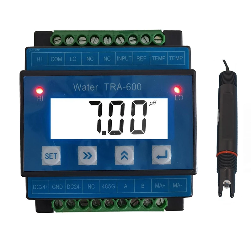
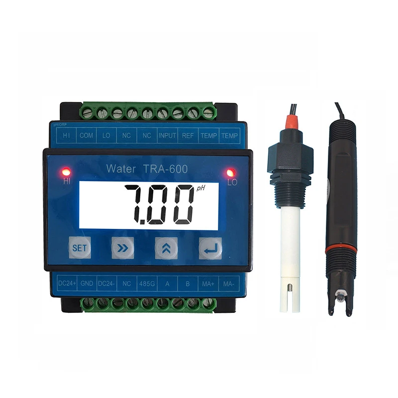
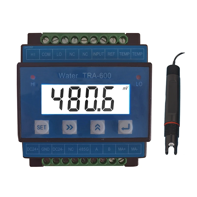
Wire Connection Details
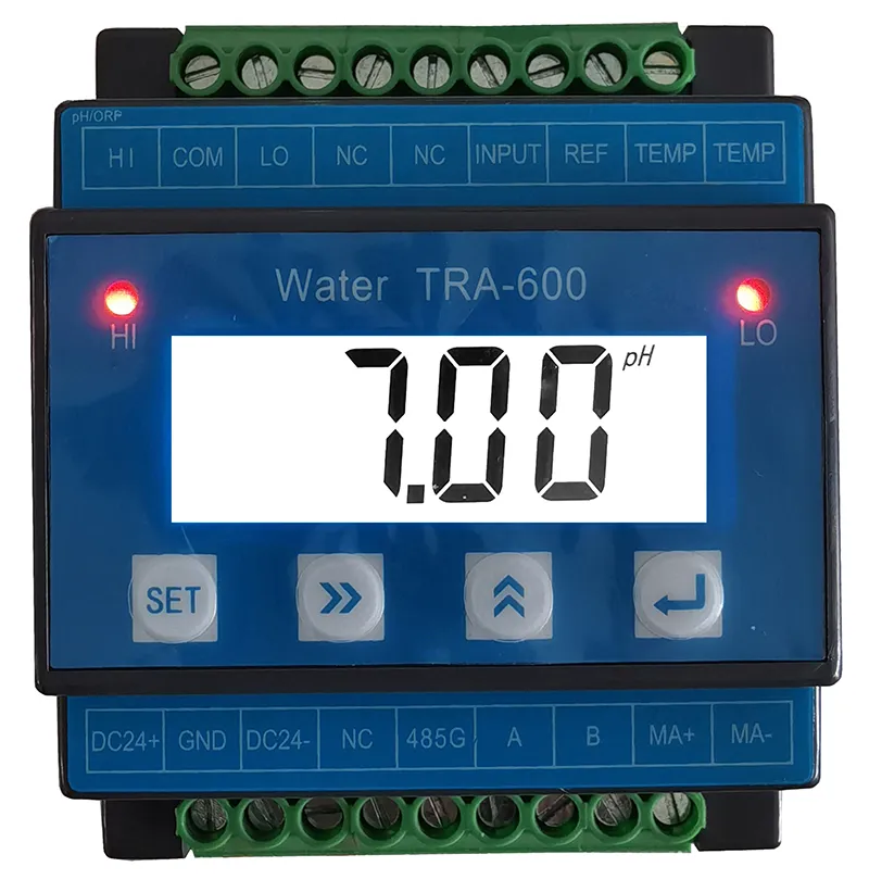
Note: The standard version is a two-wire manual temp. compensation electrode
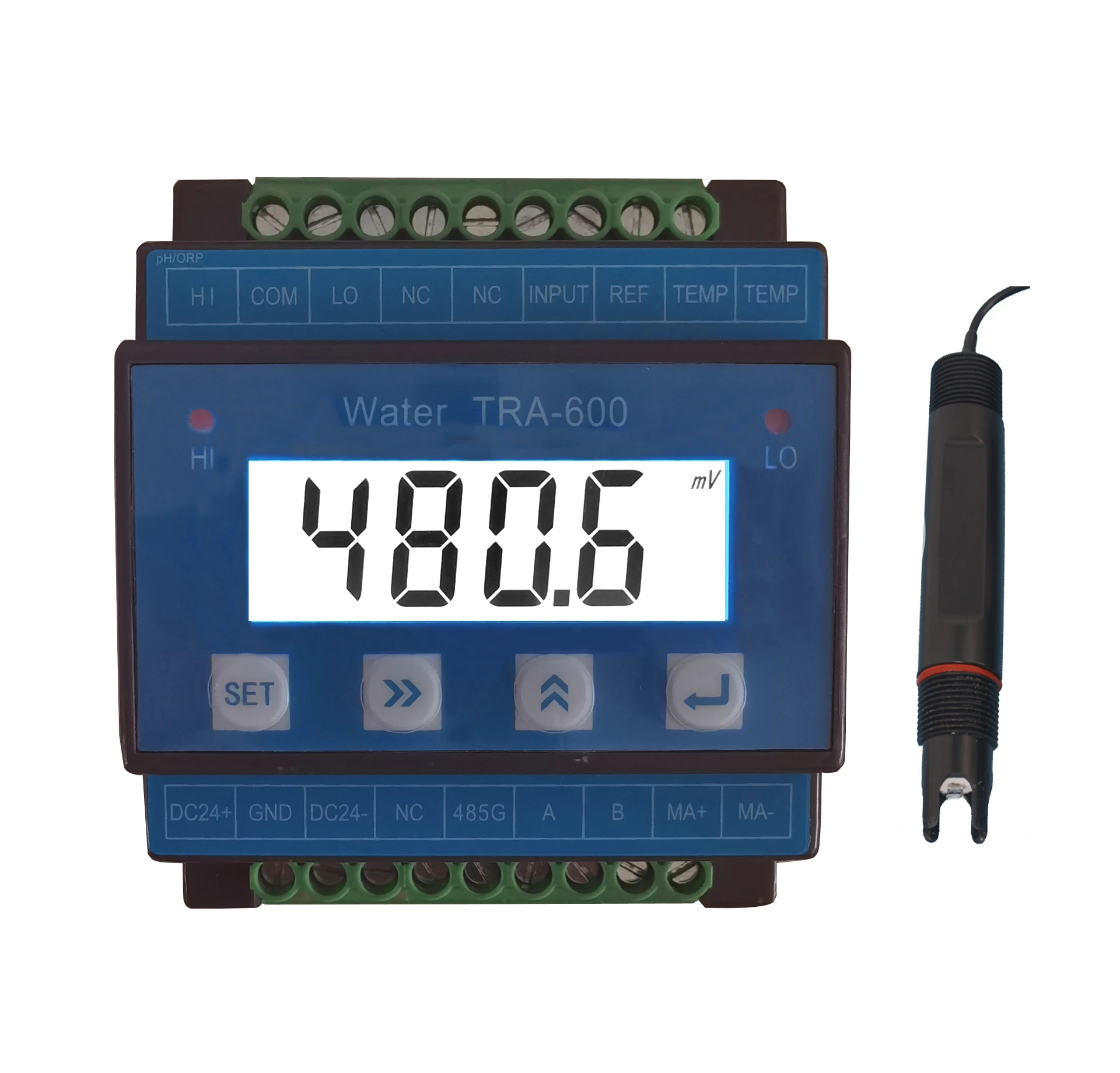
A Terminals:
|
No.
|
Terminal
|
Terminal Content
|
|
1
|
HI
|
Constantly open high limit relay alarm output
|
|
2
|
COM
|
Relay common terminal
|
|
3
|
LO
|
Constantly open low limit relay alarm output
|
|
4
|
NC
|
Empty
|
|
5
|
NC
|
Empty
|
|
6
|
INPUT
|
PH electrode signal input( Transparent wire)
|
|
7
|
REF
|
PH electrode signal ground wire( Black)
|
|
8
|
TEMP
|
Auto Temp. compensation measuring wire
|
|
9
|
TEMP
|
Auto Temp. compensation measuring wire
|
B Terminals:
|
No.
|
Terminal
|
Terminal Content
|
|
1
|
DC 24+
|
Power input +
|
|
2
|
GND
|
Equipment Ground wire
|
|
3
|
DC 24-
|
Power input -
|
|
4
|
NC
|
Empty
|
|
5
|
485G
|
RS 485 Signal Ground wire
|
|
6
|
A
|
RS485 Signal A
|
|
7
|
B
|
RS485 Signal B
|
|
8
|
MA+
|
4-20mA current signal output +
|
|
9
|
MA-
|
4-20mA current signal output -
|
Operation Of The Instrument
4.1 Soft key function
|
Soft key
|
Key function
|
Function description
|
|

|
Menu Key
|
Under Measuring status, Enter or exit related parameter “setting Menu”
|
|

|
Right shift key
|
Right Shift to select the digit of the parameter(Number flashes When selected); Up shift to browse Menu.
|
|

|
Add shift key
|
Change the selected parameter digital value and parameter shift
|
|

|
Confirm key
|
Confirm to select and enter into Menu and parameter save, check the temperature value.
|
4.2. Operation of the instrument
Under main interface,Press“ ”key to Menu interface, the detailed description as follows:
|
No.
|
Menu
|
Menu Content
|
|
1
|
Un-T
|
Measuring Unit: pH/mV shift to display
|
|
2
|
T--C
|
Temp Compensate Interface: HT-- (Manual) 、PT--( PT1000)、 NTC-(NTC10K)
|
|
3
|
HC--
|
Relay high limit close value
|
|
4
|
HO--
|
Relay high limit open value
|
|
5
|
LC--
|
Relay low limit close value
|
|
6
|
LO--
|
Relay low limit open value
|
|
7
|
DE--
|
delay x second alarm
|
|
8
|
4--A
|
4mA corresponding PH value
|
|
9
|
20-A
|
20mA corresponding PH value
|
|
10
|
ADD-
|
RS-4854 Address, default value 002
|
|
11
|
BAUD
|
RS-485 Baud Speed, default value 9600
|
|
12
|
CAL-
|
ORP Calibration Menu
|
|
13
|
FAC 0
|
Restore factory settings for user
|
|
14
|
FAC -
|
Factory setting Menu, only for factory
|
Note: After having set an option, you must press the button  to save the data.
Calibration Of Instruments
The calibration takes the form of three-point calibration. The automatic calibration protection function work in the process of calibration, illegal calibration is not executed.
Before the calibration starts, make sure that you have compounded three kinds of buffer solutions whose PH values are respectively 4.00, 6.86 and 9.18 according to relevant requirements. Before the calibration starts, the electrodes must be submerged and activated in clean water or the measured solution for 5 minutes.
The calibration methods are as follows: when it is the in the measuring state
Press the button  until the instrument display “CAL”, and it enters the calibrating state.
Press the button  , and the instrument will display “4.00”. Put the cleaned electrodes into the 4.00 compounded buffer solution, press the button
  , the controller display current buffer solution corresponding PH value, when PH value stable, and wait 3 to 5 minutes, press the button
  to save.
The controller display “6.86”, after clean the PH electrodes by pure water, put the cleaned electrodes into the 6.86 compounded buffer solution, press the button  , the controller display current buffer solution corresponding PH value ......, till 9.18 calibration finish and display OK .
During calibration, if the controller display “ ERR”, which indicate calibration failure, need to re-calibrate, if more times calibration failure, pls change the PH electrode, or contact with the supplier.
Installation Of Measuring Electrodes
The measuring electrodes are compound electrodes with plastic shells and 3/4"NPT threaded joints, Please install strictly according to the following diagrams:
3/4"NPT threaded joints.
Points for attention:
1) The electrodes shall be installed where the flow speed is steady and air bubs seldom gather or backwater which may
lead to the inaccuracy.
2) The electrode shall be submerged deep into flowing water.
3)The cable collecting PH signals which is a form of weak potential signals shall be separately wired and shall not share a protective pipe with power supply wires and control wires, so as to avoid interference.
Measuring electrodes maintenance:
1) Avoid putting the electrodes in the dry air. When the electrodes are not in use, clean them with water and then put them back into the liquid- containing case with 1 mol KCL,or put the electrodes into a container with 1 mol KCL in it.
2) The electrodes shall be cleaned regularly. If the glass bulbs of the electrodes and Polytetrafluoroethylene (PTFE) are contacted and polluted, clean them with the following agents:
① use surface active agent to get rid of grease or greasy things.
② use 10% hydrochloric acid solution to get rid of calcium precipitates or metal hydroxides.
③ use 10% hydrochloric acid solution to get rid of sulphide precipitates. Use the mixture of 10% hydrochloric acid solution and pepsins to get rid of protein adhesives.
Maintenance Of Instrument
1) The measuring electrodes are accurate parts and shall not be taken out of the measuring room unless it is necessary to do so.The PH electrode sshall be cleaned Regularly.
2) Measuring cables are special cables which shall not be replaced by other types of cables. Unqualified cables may cause big errors.
3) If the measuring electrodes are damaged or losing efficacy, purchase and replace them with the same type of compound electrodes, and calibrate them according to the fifth chapter of this manual.
4) The instrument is composed of accurate integrated circuits and electronic components and therefore shall be protected from humidity.
The Instrument As A Whole Set
| PH transmitter |
1pc |
| PH Sensor |
1pc |
| Fixing clamp |
1 pair |
| Operation manual |
1 copy |


